
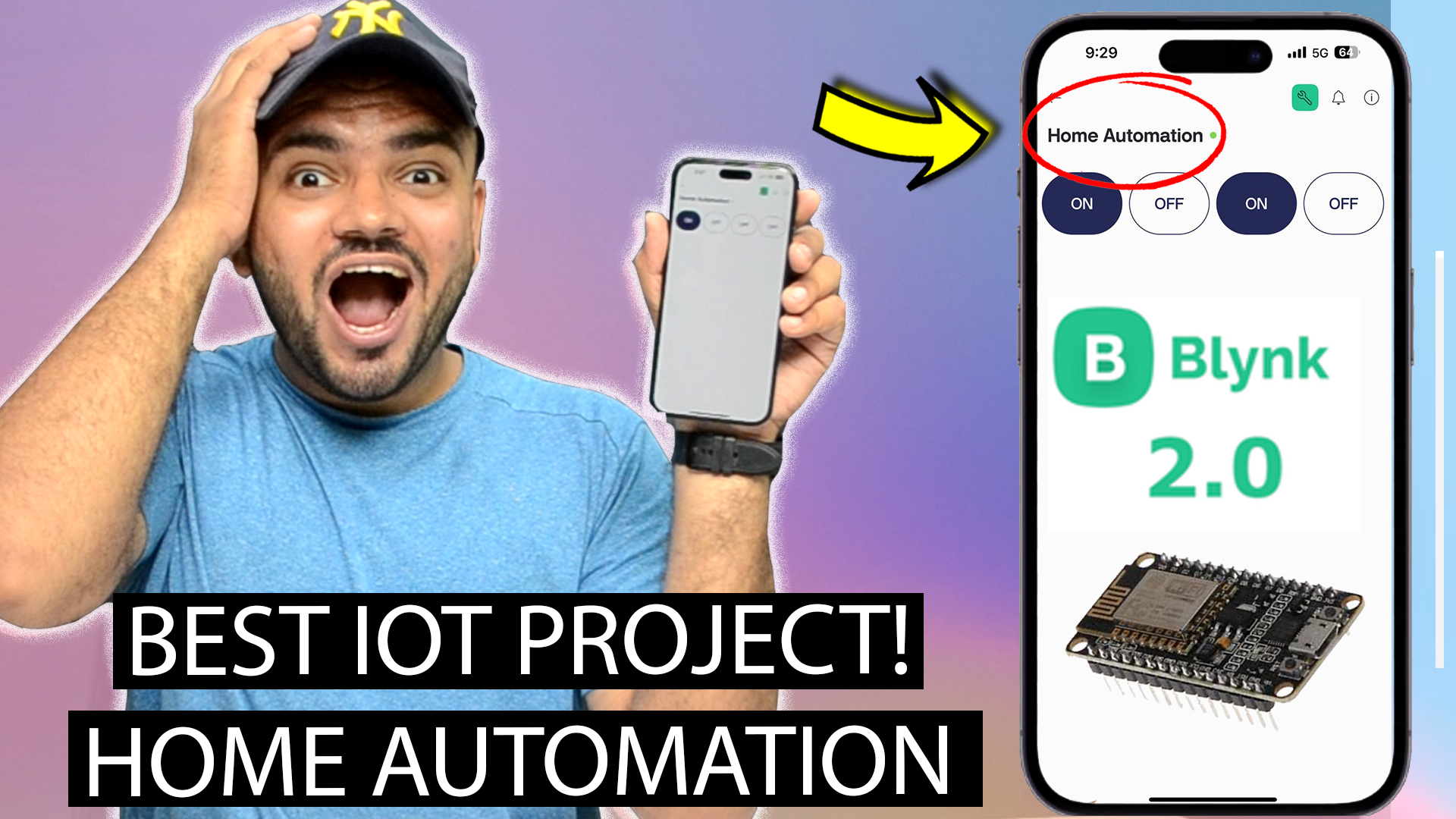
Build a Smart Home with ESP8266 NodeMCU & Blynk 2.0 | Blynk IoT
Link to buy the Entire Combo (Including Programming Bluetooth) :- Click Here
Link to buy Node MCU & 1 Channel Relay Combo (Without Coding) :- Click Here
Link to buy Node MCU & 1 Channel Relay Combo (With Coding) :- Click Here
Link to buy Node Mcu & 4 Channel Relay Combo (Without Coding) :- Click Here
Link to buy Node Mcu & 4 Channel Relay Combo (With Coding) :- Click Here
Link to buy Node Mcu & 8 Channel Relay Combo (Without Coding) :- Click Here
Link to buy Node Mcu & 8 Channel Relay Combo (With Coding) :- Click Here
IMPORTANT UPDATE
The following videos are outdated and do not work with the new Blynk 2.0 app.
1) Home Automation Using ESP8266 Nodemcu. Easy iOT Project.
2) [HINDI] Home Automation Using Node MCU & Blynk App | Control Appliances From Anywhere In The World !
Updated Video for Blynk 2.0
Build a Smart Home with ESP8266 NodeMCU & Blynk 2.0 | Blynk IoT
Link to the files used in the video
- Blynk Library :- Download
- Esp8266.h Library :- Download
- WiFi Manager.h :- Download
- Node Mcu Board Manager URL (Copy & Paste)
http://arduino.esp8266.com/stable/package_esp8266com_index.json
Updated CODE
#define BLYNK_TEMPLATE_ID “your template id”
#define BLYNK_TEMPLATE_NAME “Home Automation”
#define BLYNK_AUTH_TOKEN “your token”
#define BLYNK_PRINT Serial
#include <ESP8266WiFi.h>
#include <BlynkSimpleEsp8266.h>
#include <WiFiManager.h> // WiFi AutoConnect Library
char auth[] = BLYNK_AUTH_TOKEN;
// Pin Mapping for ESP8266 (NodeMCU)
const int pins[] = {D1, D2, D3, D4, D5, D6, D7, D8};
// GPIO Mapping: D1 (GPIO5), D2 (GPIO4), D3 (GPIO0), D4 (GPIO2), D5 (GPIO14), D6 (GPIO12), D7 (GPIO13), D8 (GPIO15)
const int pinCount = 8; // Total number of pins
void setup() {
Serial.begin(115200);
// Initialize all pins as OUTPUT
for (int i = 0; i < pinCount; i++) {
pinMode(pins[i], OUTPUT);
digitalWrite(pins[i], LOW); // Ensure all outputs start LOW
}
Serial.println(“ESP8266 Home Automation System Starting…”);
Serial.println(“Type ‘reset’ in Serial Monitor to clear Wi-Fi settings.”);
// Check if user inputs “reset” in Serial Monitor
long startTime = millis();
while (millis() – startTime < 5000) { // Wait for 5 seconds
if (Serial.available()) {
String command = Serial.readStringUntil(‘\n’);
command.trim();
if (command == “reset”) {
Serial.println(“Resetting Wi-Fi settings…”);
WiFiManager wifiManager;
wifiManager.resetSettings(); // Clear stored Wi-Fi
delay(1000);
ESP.restart(); // Restart ESP8266
}
}
}
// Normal Wi-Fi auto-connect
WiFiManager wifiManager;
wifiManager.autoConnect(“ESP8266-Setup”);
Serial.println(“Connected to Wi-Fi”);
Blynk.begin(auth, WiFi.SSID().c_str(), WiFi.psk().c_str());
Serial.println(“Connected to Blynk Cloud”);
}
// BLYNK WRITE HANDLER FOR 8 PINS
BLYNK_WRITE(V0) { togglePin(0, param.asInt()); } // D1 (GPIO5)
BLYNK_WRITE(V1) { togglePin(1, param.asInt()); } // D2 (GPIO4)
BLYNK_WRITE(V2) { togglePin(2, param.asInt()); } // D3 (GPIO0)
BLYNK_WRITE(V3) { togglePin(3, param.asInt()); } // D4 (GPIO2)
BLYNK_WRITE(V4) { togglePin(4, param.asInt()); } // D5 (GPIO14)
BLYNK_WRITE(V5) { togglePin(5, param.asInt()); } // D6 (GPIO12)
BLYNK_WRITE(V6) { togglePin(6, param.asInt()); } // D7 (GPIO13)
BLYNK_WRITE(V7) { togglePin(7, param.asInt()); } // D8 (GPIO15)
void togglePin(int index, int state) {
digitalWrite(pins[index], state ? HIGH : LOW);
Serial.print(“Pin “);
Serial.print(pins[index]);
Serial.print(” (GPIO”);
Serial.print(getGPIOFromD(pins[index])); // Get actual GPIO number
Serial.print(“) set to “);
Serial.println(state ? “HIGH” : “LOW”);
}
// Function to get GPIO number from D-pin
int getGPIOFromD(int dPin) {
switch (dPin) {
case D1: return 5;
case D2: return 4;
case D3: return 0;
case D4: return 2;
case D5: return 14;
case D6: return 12;
case D7: return 13;
case D8: return 15;
default: return -1; // Error case
}
}
void loop() {
Blynk.run();
}
IF YOU ARE GETTING A STRAY ERROR DOWNLOAD THE PROGRAM FROM HERE
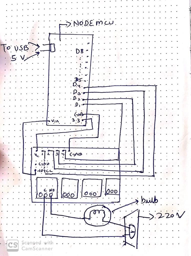
CIRCUIT DIAGRAM No.1
NOTE :- Use the given circuit diagram if your Node Mcu is able to supply the necessary 5V to the relay Board. This Setup Does not uses Arduino Uno.
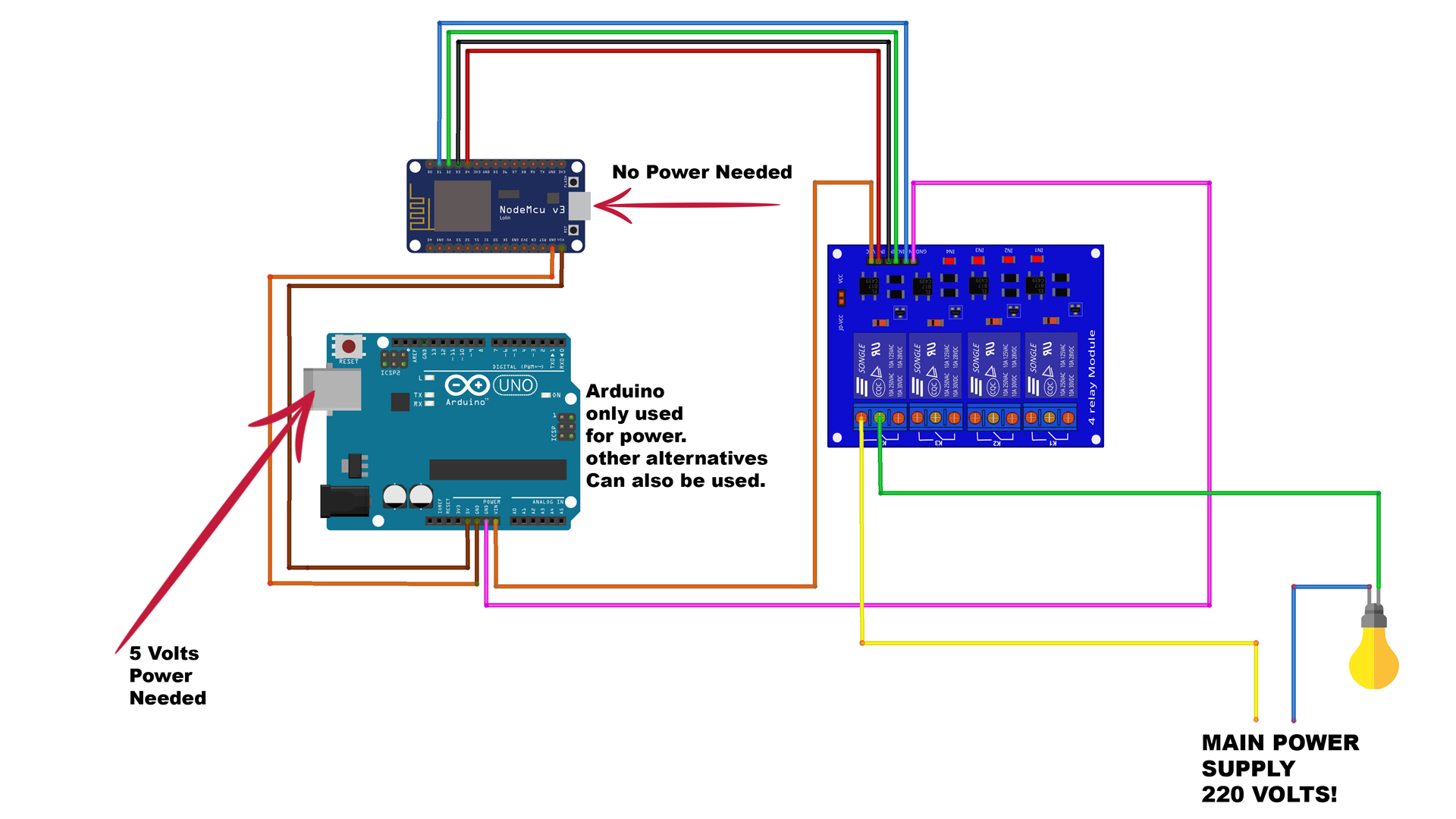
CIRCUIT DIAGRAM No.2
NOTE :- If you DONOT plan on making a case for the circuit. This uses Arduino as Node MCU didn’t supply enough power to trigger relay ON/OFF.
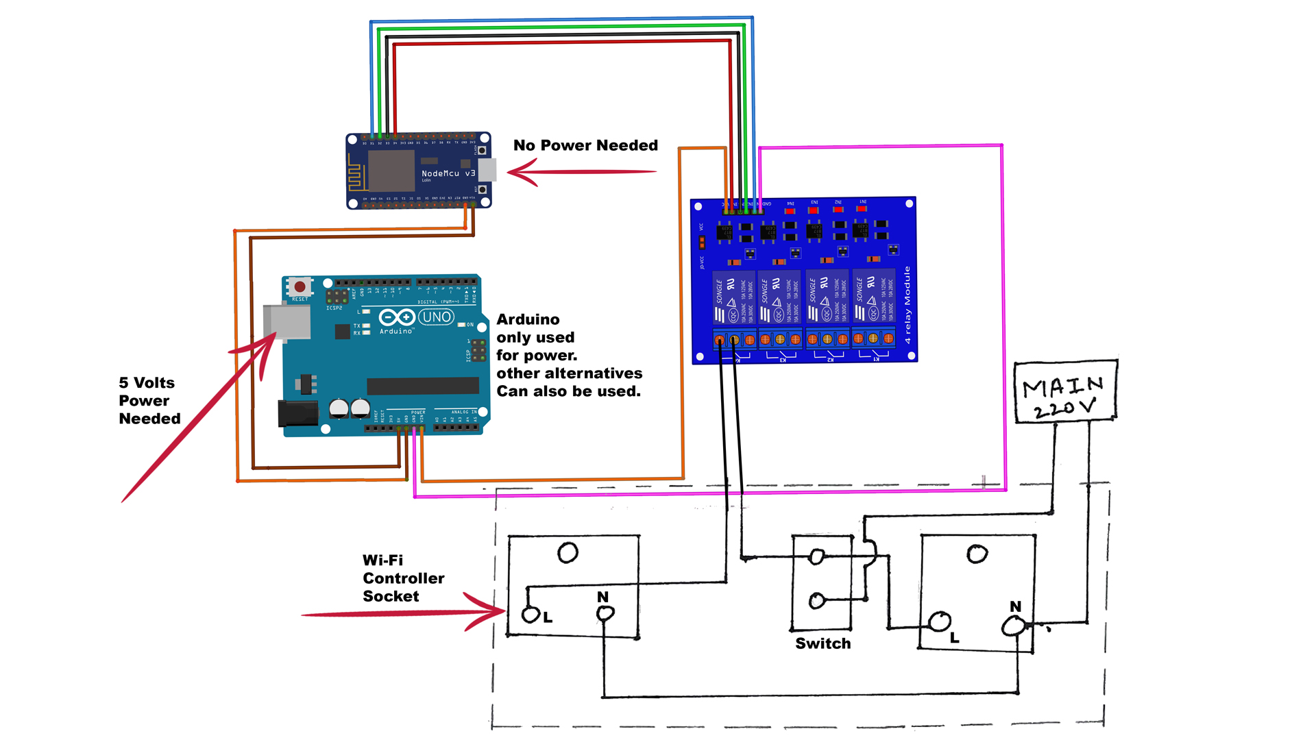
CIRCUIT DIAGRAM No.3
NOTE :- If you plan to make a circuit enclosed in a case like i showed you in the video


Wow, that’s what I was looking for, what a information! present here at this webpage, thanks admin of this web page.|