
Code & Circuit diagram for Keypad Arduino Security System
🔐 Arduino Keypad Security System
If you want to buy the entire package with a re-programmable Arduino
Click Here
💻 Arduino Code
Upload the following code to your Arduino using the Arduino IDE:
|
1 2 3 4 5 6 7 8 9 10 11 12 13 14 15 16 17 18 19 20 21 22 23 24 25 26 27 28 29 30 31 32 33 34 35 36 37 38 39 40 41 42 43 44 45 46 47 48 49 50 51 52 53 54 55 |
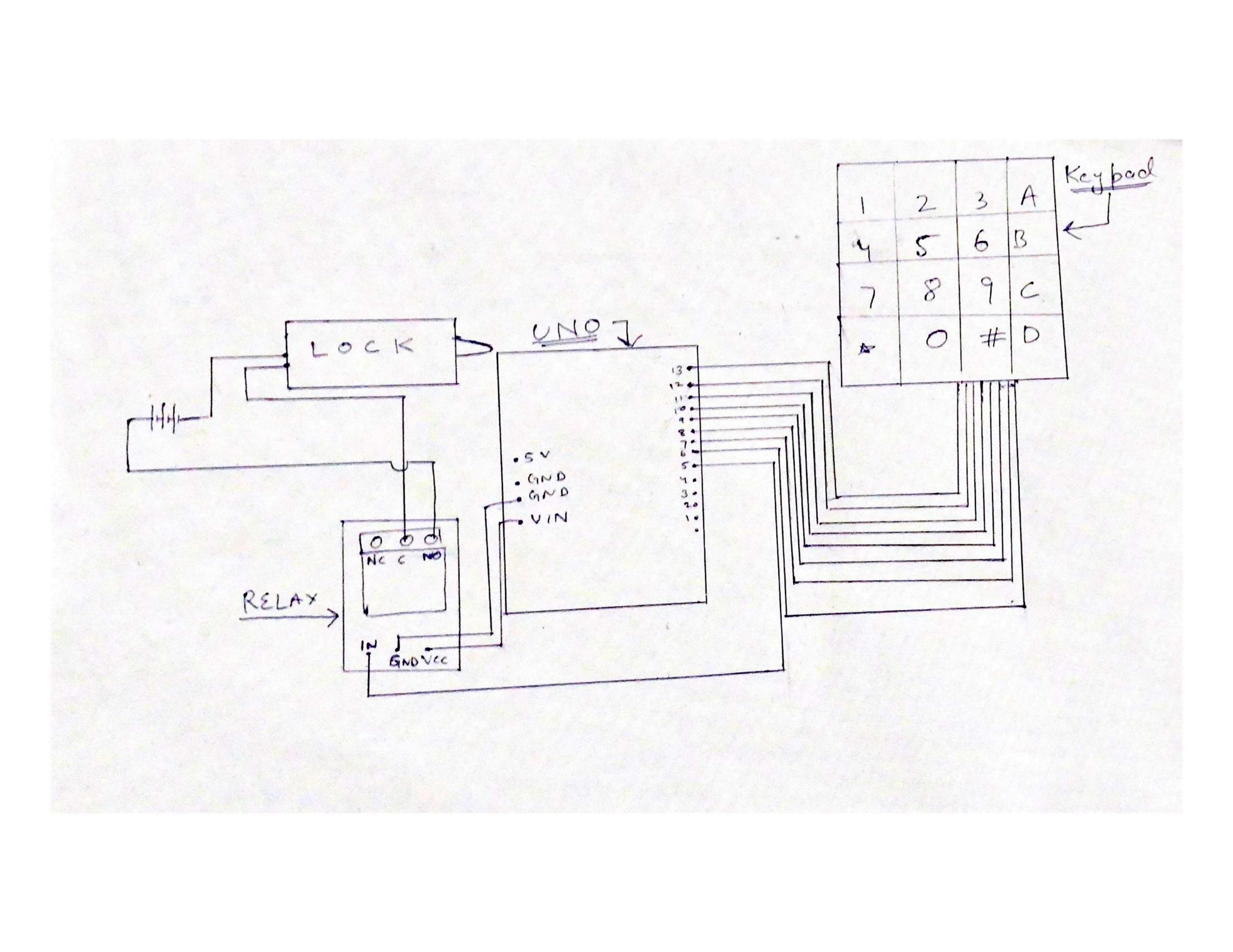
#include <Keypad.h> char *password = "3690"; // Change this to modify password int position = 0; const byte ROWS = 4; const byte COLS = 4; char keys[ROWS][COLS] = { {'1','2','3','A'}, {'4','5','6','B'}, {'7','8','9','C'}, {'*','0','#','D'} }; byte rowPins[ROWS] = {13, 12, 11, 10}; byte colPins[COLS] = {9, 8, 7, 6}; Keypad keypad = Keypad(makeKeymap(keys), rowPins, colPins, ROWS, COLS); int Lock = 5; // Relay connected to pin 5 void setup() { pinMode(Lock, OUTPUT); LockedPosition(true); } void loop() { char key = keypad.getKey(); if (key == '*' || key == 'A') { position = 0; LockedPosition(true); } if (key == password[position]) { position++; } if (position == 4) { // Change if password length increases LockedPosition(false); } delay(100); } void LockedPosition(int locked) { if (locked) { digitalWrite(Lock, LOW); } else { digitalWrite(Lock, HIGH); } } |
If you are getting a stray error, download the code from
here
.
🔌 Circuit Diagram