
Code and Circuit Diagram for Smart Locking Door System Using RFID Sensor and Arduino Board
#include <SPI.h>
#include <MFRC522.h>
#define SS_PIN 10
#define RST_PIN 9
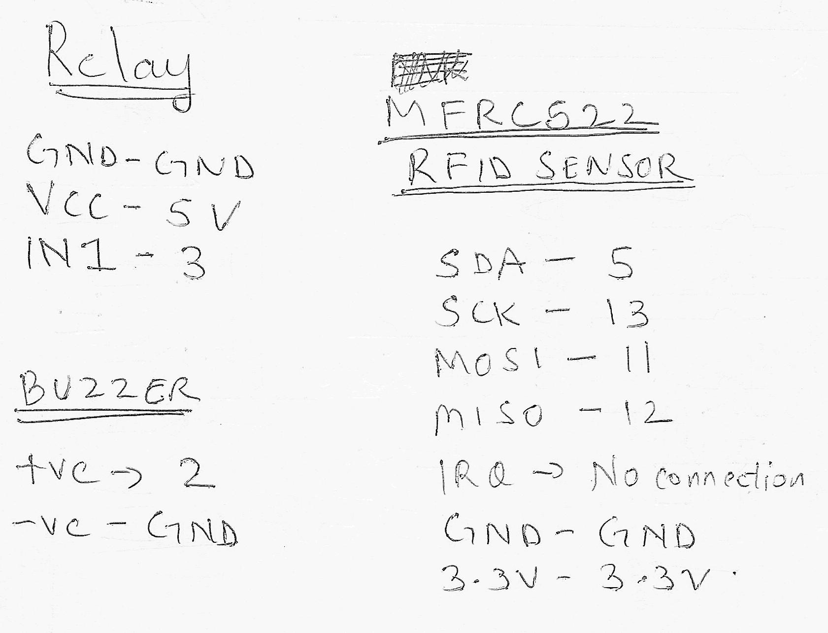
#define RELAY 3 //connect the relay to number 3 pin
#define BUZZER 2 // connect the buzzer to 2 pin
#define ACCESS_DELAY 2000
#define DENIED_DELAY 1000
MFRC522 mfrc522(SS_PIN, RST_PIN); // Create MFRC522 instance.
void setup()
{
Serial.begin(9600); // Initiate a serial communication
SPI.begin(); // Initiate SPI bus
mfrc522.PCD_Init(); // Initiate MFRC522
pinMode(RELAY, OUTPUT);
pinMode(BUZZER, OUTPUT);
noTone(BUZZER);
digitalWrite(RELAY, HIGH);
Serial.println(“Put your card to the reader for scanning …”);
Serial.println();
}
void loop()
{
// Look for new cards
if ( ! mfrc522.PICC_IsNewCardPresent())
{
return;
}
// Select one of the cards
if ( ! mfrc522.PICC_ReadCardSerial())
{
return;
}
//Show UID on serial monitor
Serial.print(“UID tag :”);
String content= “”;
byte letter;
for (byte i = 0; i < mfrc522.uid.size; i++)
{
Serial.print(mfrc522.uid.uidByte[i] < 0x10 ? ” 0″ : ” “);
Serial.print(mfrc522.uid.uidByte[i], HEX);
content.concat(String(mfrc522.uid.uidByte[i] < 0x10 ? ” 0″ : ” “));
content.concat(String(mfrc522.uid.uidByte[i], HEX));
}
Serial.println();
Serial.print(“Message : “);
content.toUpperCase();
if (content.substring(1) == “AB CD EF GH”) // enter your own card number after copying it from serial monitor
{
Serial.println(“Authorized access”);
Serial.println();
delay(500);
digitalWrite(RELAY, LOW);
delay(ACCESS_DELAY);
digitalWrite(RELAY, HIGH);
}
else {
Serial.println(” Access denied”);
tone(BUZZER, 300);
delay(DENIED_DELAY);
noTone(BUZZER);
}
}
If you are getting a stray error then download the program from here – click here to download
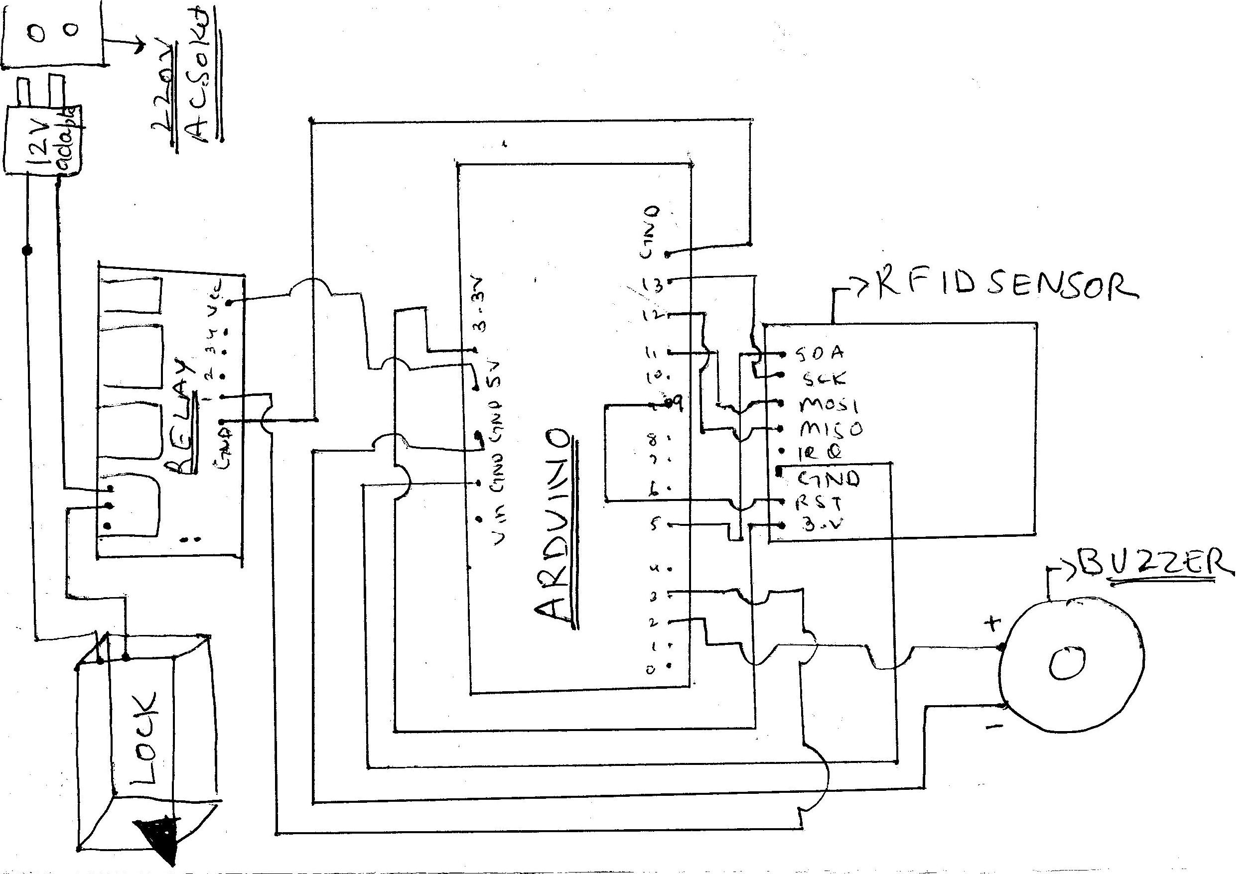
Circuit Diagram –

Here is real awarding an keep to winning. harshsharmatechnicals.com
http://bit.ly/2NJvUmB